Designed from scratch in SolidWorks, analyzed in XFoil, XFLR5, and ANSYS Fluent, hand-built from EPS foam, and flight-tested over 12 flights. Solo project, 2 months, about $140 in components.
- Wing peak L/D (XFLR5)
- ≈ 15
- Cruise CL @ 10 m/s
- 0.80
- Aspect ratio
- 5.2
- Weight
- 0.6 kg
- Flights, ~1 hr airtime
- 12

Overview
I took this aircraft from requirements to flight on my own: CAD, airfoil selection, 2D and 3D aerodynamic analysis, fabrication, and iterative flight testing. The main constraint was low Reynolds number (Re ≈ 100k), where airfoil performance degrades and small design choices matter.
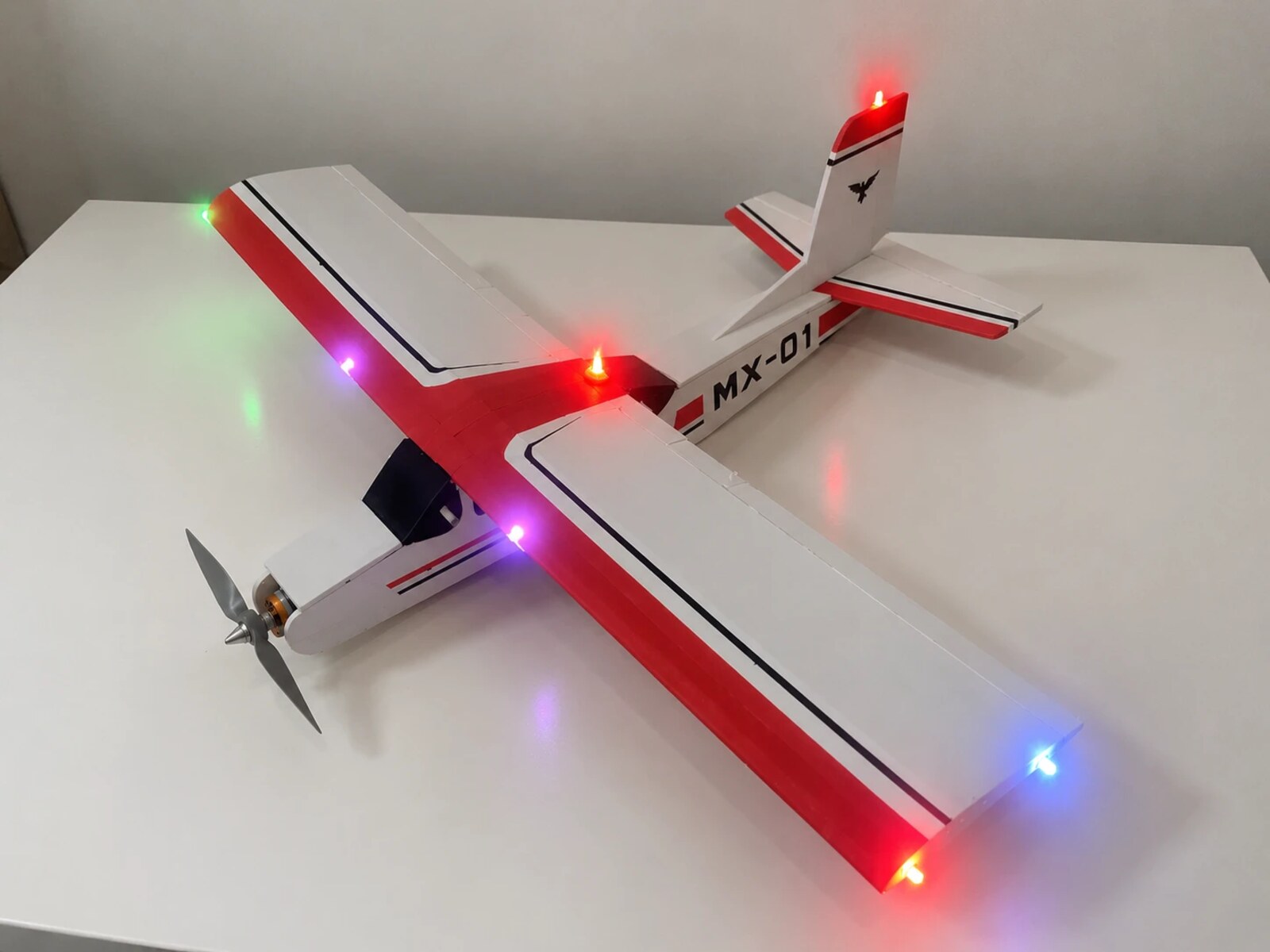
Specifications
| Parameter | Value |
|---|---|
| Wing | 0.79 m span, 0.15 m chord, 0.12 m², rectangular, Clark Y |
| Horizontal stabilizer | 0.29 m span, 0.11 m root / 0.07 m tip chord, flat plate |
| Vertical stabilizer | 0.01 m², flat plate |
| Tail arm | 0.27 m (horizontal tail volume ≈ 0.39) |
| Fuselage | 0.60 m, CG at 0.35 m from nose |
| AUW | 0.6 kg (scale-measured), wing loading ≈ 49 N/m² |
| Propulsion | A2212 1400 kV motor, 30 A ESC, 8×6 prop, 2S 2200 mAh LiPo |
| Control | FlySky FS-i6 / iA6B receiver, 4× SG90 servos |
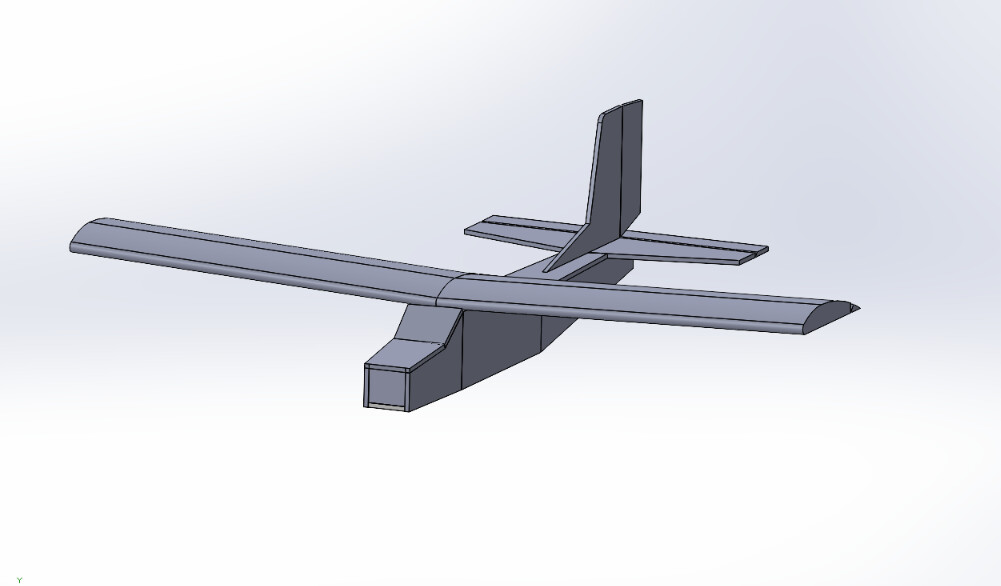
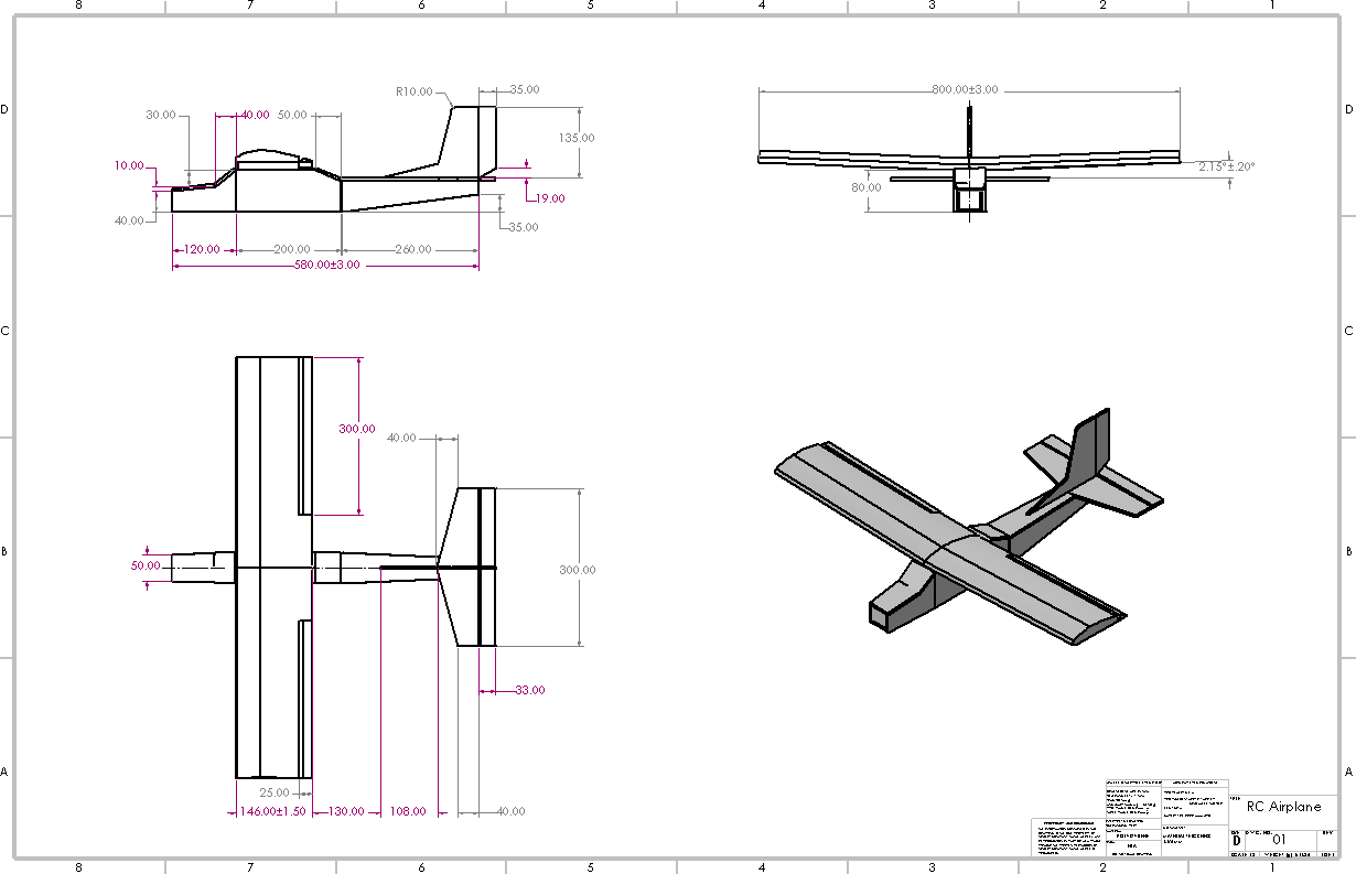
1. Requirements and sizing
- Targeted a 10 m/s cruise at 0.6 kg, which gives Re ≈ 100k and a required CL of ≈ 0.80 on the 0.12 m² wing.
- Chose a rectangular planform and flat-bottom airfoil to keep foam construction simple.
2. Airfoil selection
- Selected the Clark Y for favourable low-Re performance and simple geometry. Imported its coordinates from airfoiltools.com into XFLR5.
- Ran XFoil polars at Re = 50k, 100k, and 150k:
- Lift slope ≈ 0.1 per degree
- CLmax ≈ 1.38 at Re = 100k
- CD ≈ 0.0173 at CL = 0.7
- Peak CL/CD ≈ 53 at Re = 100k
- Identified a laminar separation bubble at Re = 50k that drops peak CL/CD to ≈ 29 and marks the slow end of the envelope.
3. 3D wing analysis (XFLR5)
- Built the rectangular wing with the viscous polars and ran lifting-line analysis at 10 m/s.
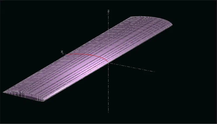
- Wing lift slope ≈ 0.077 per degree. Peak L/D ≈ 15.0 at α = 4° (CL ≈ 0.57).
- At the 10 m/s cruise point (CL = 0.80, α ≈ 7°), L/D ≈ 14. Cruising at 11–12 m/s would put cruise at the peak.
- Used the results to set a 2.3° wing mounting incidence that keeps the fuselage near level in cruise.
4. CFD cross-check (ANSYS Fluent, wing only)
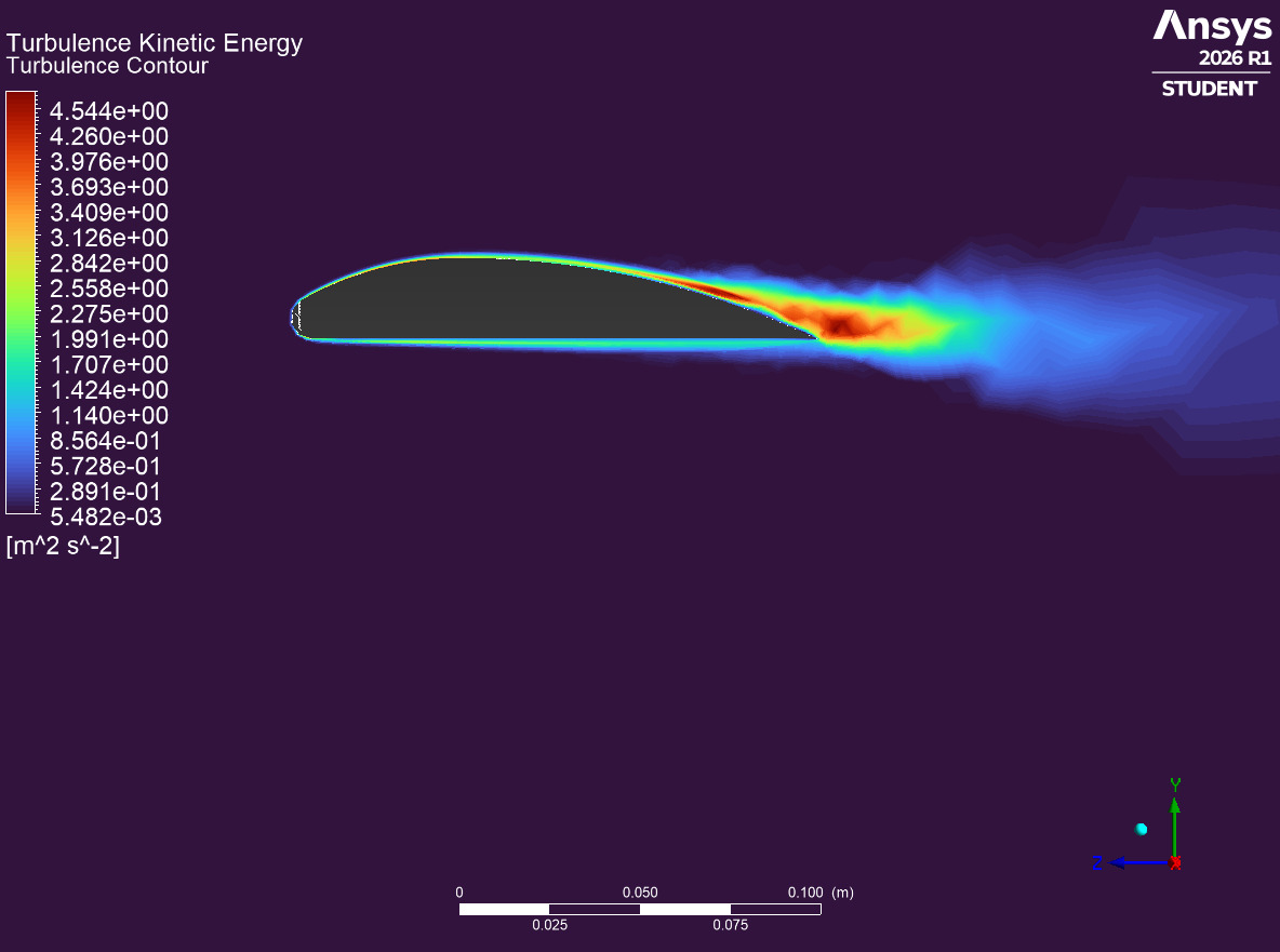
I ran 3D CFD on the wing alone and compared it against XFLR5.
| α (°) | XFLR5 CL | XFLR5 L/D | Fluent CL | Fluent CD | Fluent L/D | CL diff (%) | L/D diff (%) |
|---|---|---|---|---|---|---|---|
| 0 | 0.231 | 10.2 | TBD | TBD | TBD | TBD | TBD |
| 2 | 0.411 | 14.1 | TBD | TBD | TBD | TBD | TBD |
| 4 | 0.574 | 15.0 | TBD | TBD | TBD | TBD | TBD |
| 6 | 0.728 | 14.5 | TBD | TBD | TBD | TBD | TBD |
| 8 | 0.873 | 13.3 | TBD | TBD | TBD | TBD | TBD |
Fluent setup: turbulence model TBD, mesh size TBD, domain TBD.
I used pressure, velocity, and turbulence fields to see where lift and drag originate.
5. Fabrication
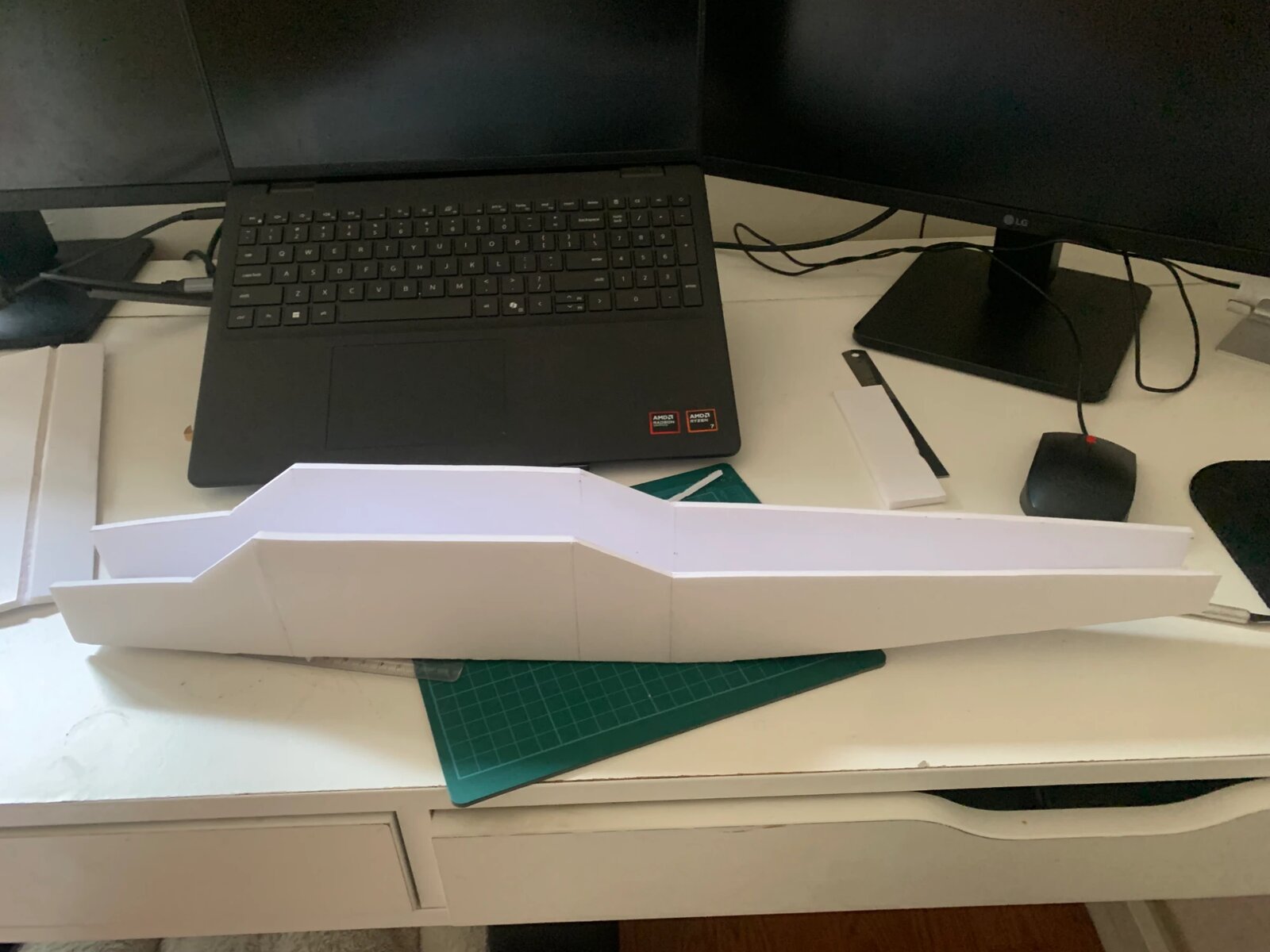
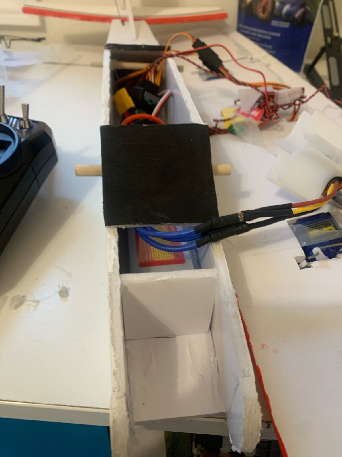
- EPS foam airframe for low weight and fast shaping, with a flat-plate tail.
- Designed the motor mount in SolidWorks, exported a DXF, and laser-cut it from hardboard.
- Wired and commissioned the full propulsion and control system.
6. Flight testing and iteration
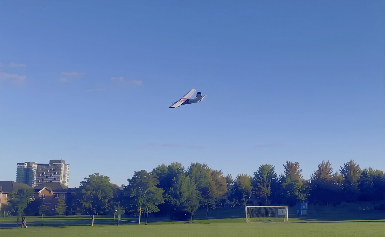
12 flights, about 1 hour of total airtime, with trim adjustments and crash repairs between flights. The controls test and the maiden test flight are the two videos at the top of this page.
- Vibration: torque ripple from the motor caused vibration. I added a second hardboard motor mount to stiffen the structure and reduce it.
- Control sensitivity: the aircraft was overly agile, with very sensitive controls. I set transmitter expo to 30% to soften response around neutral.
Key takeaways
- Cruise CL and best-L/D CL are separate targets, and low-Re airfoil behaviour (50k vs 100k+) shapes the whole flight envelope.
- Cross-checking a fast tool (XFLR5) against CFD (Fluent) catches setup errors early.
- Flight testing exposed problems the analysis did not: vibration and control sensitivity.